K7DD
Advanced Motor Condition Monitoring Device
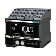
Implementing predictive maintenance with real-time condition monitoring of variable speed motors
Related Contents
- Features
- Lineup
- Specifications
- Dimensions
- Catalog / Manual / CAD / Software
last update: February 1, 2024
Ratings and Specifications
| Item | Specifications | |
|---|---|---|
| Operation
power supply |
Power supply voltage
and frequency |
K7DD-PQMA: 100 to 240 V AC, 50/60 Hz
K7DD-PQMD: 24 V DC |
| Operating power
supply voltage range |
85% to 110% of the rated voltage | |
| Operating frequency
range |
45 to 65 Hz | |
| Power consumption | K7DD-PQMA: 15.7 VA max. (100 to 240 V AC) | |
| K7DD-PQMD: 5.2 W max. (24 V DC) | ||
| Recommend
external fuse |
T2A, time delay, high-breaking capacity | |
| Ambient operating temperature | -10 to 55°C | |
| Ambient operating humidity | 25% to 85% | |
| Storage temperature | -20 to 65°C (with no condensation or icing) | |
| Altitude | 2,000 m max. | |
| Insulation resistance | 20 mΩ min.
Between the power supply terminals and the other terminals; Between all the terminals and the case; Between (communications terminals + trigger input terminals + alarm output terminals) and the other terminals; Between (voltage input terminals + CT input terminals) and the other terminals |
|
| Dielectric strength | 2,000 V AC for 1 minute
Between the power supply terminals and the other terminals; Between all the terminals and the case; Between (communications terminals + trigger input terminals + alarm output terminals) and the other terminals; Between (voltage input terminals + CT input terminals) and the other terminals |
|
| Vibration resistance | Frequency 10 to 55 Hz, 0.35-mm single amplitude, acceleration 50 m/s²,
10 sweeps of 5 min each in X, Y, and Z directions |
|
| Shock resistance | 100 m/s2, 3 times each in X, Y, and Z axes, 6 directions | |
| Degree of protection | IP20 | |
| Terminal block type | Push-In Plus | |
| Exterior color | Black (Munsell N 1.5) | |
| Mounting | DIN Track | |
| Weight | Approx. 360 g | |
| Wiring
material |
Wire type | Solid or Stranded wire |
| Wiring material | Copper | |
| Recommended wires | 0.25 to 1.5 mm2
AWG 24 to AWG 16 |
|
| Stripping length
(without ferrules) |
8 mm *, 10 mm, 12 mm * without ferrules | |
| Installation environment | Operation voltage: EN/IEC 61010-1 Pollution Degree 2, Overvoltage category II | |
| Measurement circuit: EN/IEC 61010-2-030 Pollution Degree 2, CAT II 600 V or
CAT III 300 V |
||
| Industrial electromagnetic
environment |
EN/IEC 61326-1 Industrial electromagnetic environment | |
| Safety standards | UL61010-1, Korean Radio Waves Act (KS C 9610-6-2, KS C 9811), RCM, UKCA | |
Measurement Specifications
| Item | Specifications | Conditions | |
|---|---|---|---|
| Input range
(Displayable range) |
Current | 5 A range: 0.275 to 5.5 A
25 A range: 1.375 to 27.5 A 100 A range: 5.5 to 110.0 A 200 A range: 11.0 to 220.0 A 400 A range: 22.0 to 440.0 A |
Defined by R.M.S. values using a sine wave.
The power frequency must be within the acceptable range. |
| Voltage | 150 V range: 8.3 to 165.0 V
300 V range: 16.5 to 330.0 V 600 V range: 33.0 to 660.0 V |
||
| Power
frequency |
40 to 250 Hz | Sine-wave or single-order harmonic content must
be 20% or less. |
|
| Input ratings
(Measurement accuracy guarantee range) |
Current | 5 A range: 1.0. to 5.0 A
25 A range: 5.0 to 25.0 A 100 A range: 25.0 to 100.0 A 200 A range: 100.0 to 200.0 A 400 A range: 200.0 to 400.0 A |
Defined by R.M.S. values using a sine wave.
The power frequency must be within the acceptable range. |
| Voltage | 150 V range: 75.0 to 150.0 V
300 V range: 150.0 to 300.0 V 600 V range: 300.0 to 600.0 V |
||
| Power
frequency |
45 to 245 Hz | Since wave | |
| Measurement
accuracy (Ambient temperature: 10 to 30°C) |
Current | Absolute accuracy: 0.5%FS±1digit
Repeat accuracy: ±1%rdg±1digit |
Not including accuracy variation of CTs
The power frequency must be within the rated range. |
| Voltage | Absolute accuracy: 0.5%FS±1digit
Repeat accuracy: ±1%rdg±1digit |
The power frequency must be within the rated range. | |
| Active/
reactive power |
Absolute accuracy: ±2%FS±1digit
Repeat accuracy: ±1%rdg±1digit |
Power factor 1
The power frequency must be within the rated range. |
|
| Power
frequency |
Absolute accuracy: 0.5%FS±1digit
Repeat accuracy: ±1%rdg±1digit |
Sine wave | |
Measurement Target
The K7DD can measure both the voltage and current or only the current of power lines that drive motors, valves, and other measurement targets.
There are three wiring methods depending on the phase-wire system of the power supply.
Calculable Feature List
| Name | Single-phase current | 3P3W2M | 3P4W | |
|---|---|---|---|---|
| Voltage | R.M.S. value | --- | Possible | Possible |
| Fundamental amplitude | --- | Possible | Possible | |
| Waveform peak + | --- | Possible | Possible | |
| Waveform peak - | --- | Possible | Possible | |
| Total harmonic distortion | --- | Possible | Possible | |
| Unbalance factor | --- | Possible | Possible | |
| Current | R.M.S. value | Possible | Possible | Possible |
| Fundamental amplitude | Possible | Possible | Possible | |
| Waveform peak + | Possible | Possible | Possible | |
| Waveform peak - | Possible | Possible | Possible | |
| Total harmonic distortion | Possible | Possible | Possible | |
| Unbalance factor | --- | Possible | Possible | |
| Power | Active | --- | Possible | Possible |
| Deactive | --- | Possible | Possible | |
| Apparent | --- | Possible | Possible | |
| Power factor | --- | Possible | Possible | |
| Harmonic | Current content rate | Possible | Possible | Possible |
| Frequency | Possible | Possible | Possible | |
When this unit is combined with Condition Monitoring Configuration Tool software, all of the above features can be checked.
The measurement values that can be checked by this unit alone are as follows.
R.M.S. voltage, R.M.S. current, voltage fundamental amplitude, current fundamental amplitude, active power, power factor, frequency, voltage total harmonic distortion, and current total harmonic distortion
Trigger Input Terminals
| Item | Specifications |
|---|---|
| Input type | NPN open-collector |
| Residual voltage at short circuit | 1.5 V max. |
| Open leakage current | 0.1 mA max. |
| ON current at short circuit | Approx. 7 mA |
| Minimum detection time | Received as a valid continuous input for at least 50 ms for both ON and OFF. |
Output Specifications of Transistor Output Terminals
| Item | Specifications | |
|---|---|---|
| Transistor output
(Alarm output, Output at error) |
Contact form | NPN open collector |
| Rated voltage | 24 V DC (maximum voltage: 26.4 V DC) | |
| Maximum current | 50 mA | |
| Leakage current when power turning OFF | 0.1 mA max. | |
| Residual voltage | 1.5 V max. | |
Communications Specifications
| Item | Specifications | |
|---|---|---|
| RS-485
communications 1 RS-485 communications 2 |
Transmission path
connection method |
RS-485: Multidrop |
| Communications method | RS-485 (2-wire, half duplex) | |
| Cable length | When the baud rate is 115.2 kbps or less, the maximum length is
500 m with a shielded twisted-pair cable. When the baud rate is 230.4 kbps, the maximum length is 200 m with a shielded twisted-pair cable. |
|
| Protocol | Modbus RTU | |
| Baud rate | 9.6 kbps/ 19.2 kbps/ 38.4 kbps/ 57.6 kbps/ 115.2 kbps/ 230.4 kbps | |
| Data length | Always 8 bits | |
| Stop bits | Always 1 bit (with parity being even/odd)
Always 2 bits (with parity being none) |
|
| Connection configurations | 1:1 or 1:N | |
| Maximum number of Units | 32 Units (including the host system) | |
| Parity | None/Even/Odd | |
| Send wait time | 0 to 99 ms | |
Ratings and Specifications of CT*1
| Model | K6CM-
CICB005(-C) |
K6CM-
CICB025(-C) |
K6CM-
CICB100(-C) |
K6CM-
CICB200(-C) |
K6CM-
CICB400(-C) |
|---|---|---|---|---|---|
| Construction | Internal split type | ||||
| Primary-side rated current | 5 A | 25 A | 100 A | 200 A | 400 A |
| Rated voltage | 600 V AC | ||||
| Secondary winding | 3,000 turns | 6,000 turns | |||
| Insulation resistance | Between output terminal and case: 50 mΩ min | ||||
| Dielectric strength | Between output terminal and case: 2,000 V AC for 1 minute | ||||
| Protective element | 7.5 V clamp element | ||||
| Allowable number of attachments
and detachments |
100 times | ||||
| Diameter of wire attachable *2 | 7.9 mm dia.
max. |
9.5 mm dia.
max. |
14.5 mm dia.
max. |
24.0 mm dia.
max. |
35.5 mm dia.
max. |
| Operating temperature and
humidity range |
-20 to 60°C, 25% to 85% (with no condensation or icing) | ||||
| Storage temperature and
humidity range |
-30 to 65°C, 25% to 85% (with no condensation or icing) | ||||
| Supplied cable length | 2.9 m | ||||
| Supplied cable terminal | K7DD side: Ferrule, CT side: Round crimp terminal | ||||
| Degree of protection | IP20 | ||||
*1. To comply with UL certification, refer to Conformance to Safety Standards.
*2. When you use a flat wire, refer to the outline dimensional drawing of the relevant CT and use a CT with a larger diameter.
However, use the CT within the range of its rated current.
*2. When you use a flat wire, refer to the outline dimensional drawing of the relevant CT and use a CT with a larger diameter.
However, use the CT within the range of its rated current.
last update: February 1, 2024