Discontinued On Mar. 2019
G2RV
Slim Relay
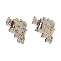
The World's First Industrial Slim Relay
* Information in this page is a reference that you created on the basis of information in the product catalog before the end of production, may be different from the current situation, such as goods for / supported standards options / price / features of the product. Before using, please check the compatibility and safety system.
Related Contents
- Features
- Lineup
- Specifications
- Dimensions
- Catalog / Manual / CAD / Software
last update: November 4, 2014
Input Ratings
|
Rated
voltage |
Rated current *1 |
Must operate
voltage |
Must release
voltage |
Power consumption | Input voltage | |||
|---|---|---|---|---|---|---|---|---|
| AC | DC | % of rated voltage |
AC (VA)
Approx. |
DC (mW)
Approx. |
% of rated
voltage |
|||
| 50 Hz | 60 Hz | |||||||
| 12 VDC | --- | --- | 27.2 mA | 0.8 | 0.1 | --- | 300 mW | ±10% |
| 24 VDC | --- | --- | 13.3 mA | --- | 300 mW | |||
| 24 VAC/DC | 21.1 mA | 22.5 mA | 13.0 mA | 0.5 VA | 300 mW | |||
| 48 VAC/DC | 8.5 mA | 9.0 mA | 5.2 mA | 0.4 VA | 250 mW | |||
| 110 VAC | 7.1 mA | 7.5 mA | --- | 0.8 VA | --- | |||
| 230 VAC | 7.3 mA | 7.9 mA | --- | 1.7 VA | --- | |||
*1. Rated currents are measured at 23 degrees Celsius (ambient)
Contact Ratings
| Item | Standard type (G2RV-SL700, 500, 701, 501) | Input type (G2RV-SL700-AP, 500-AP) *2 | |
|---|---|---|---|
| Number of poles | 1 pole | ||
| Load | Resistive load
(cosφ = 1) |
Inductive load
(cosφ = 0.4, L/R = 7 ms) |
Resistive load
(cosφ = 1) |
| Rated load | 6 A at 250 VAC;
6 A at 30 VDC |
2.5 A at 250 VAC;
2 A at 30 VDC |
50 mA at 30 VAC;
50 mA at 36 VDC |
| Rated carry current | 6 A | 50 mA | |
| Max. switching voltage | 400 VAC, 125 VDC | 30 VAC, 36 VDC | |
| Max. switching current | 6 A | 50 mA | |
| Max. switching power | 1,500 VA
180 W |
500 VA
60 W |
—— |
|
Failure rate (reference
value) *1 |
10 mA at 5 VDC (P level) | 1 mA at 100 mVDC (P level) | |
*1. P level: λ60 = 0.1 × 10⁻⁶/operation
*2. If a gold layer is destroyed, contact ratings of standard type are applicable.
Characteristics
| Item | Standard type (G2RV-SL700, 500, 701, 501) | Input type (G2RV-SL700-AP, 500-AP) |
|---|---|---|
| Contact resistance | 100 mΩ max. | |
| Operate (set) time | 20 ms max. | |
| Release time | 40 ms max. | |
| Max. operating frequency | Mechanical: 18,000 operations/hr
Electrical: 1,800 operations/hr (under rated load) |
|
| Insulation resistance | 1,000 MΩ min. (at 500 VDC) | |
| Dielectric strength | 4,000 VAC, 50/60 Hz for 1 min between coil and contacts*;
1,000 VAC, 50/60 Hz for 1 min between contacts of same polarity |
|
| Vibration resistance | Destruction: 10 to 55 to 10 Hz, 0.50 mm single amplitude (1.0 mm double amplitude)
Malfunction: 10 to 55 to 10 Hz, 0.50 mm single amplitude (1.0 mm double amplitude) |
|
| Shock resistance | Destruction: 1,000 m/s2
Malfunction: 200 m/s2 when energized; 100 m/s2 when not energized |
|
| Endurance | Mechanical: 5,000,000 operations min.
Electrical: 100,000 Typical; NO 70,000 operations min.; NC 50,000 operations min. |
Mechanical: 5,000,000 operations min.
Electrical: 5,000,000 operations min. |
| Ambient temperature | Operating: -40°C to 55°C (with no icing or condensation) | |
| Ambient humidity | Operating: 5% to 85% | |
| Weight | Approx. 35 g | |
| Overvoltage category | III | |
| Pollution degree | 2 | |
| Contact material | AgSnIn | AgSnIn + Gold Plating |
| Creepage distance | 7.0 mm | |
| Clearance distance | 5.5 mm | |
Note: Values in the above table are the initial values.
Approved Standards
UL 508 (File No. E41643)
| Model | Contact form | Coil ratings | Contact ratings | Operations |
|---|---|---|---|---|
| G2RV-SL Series | SPDT | 12 to 48 VDC
24 to 230 VAC |
250 VAC 6 A (Resistive Load)
30 VDC 6 A (Resistive Load) 400 VAC 2 A (Resistive Load) |
6,000 |
IEC/VDE (EN 61810)
| Contact form | Coil ratings | Contact ratings | Operations |
|---|---|---|---|
| SPDT | 12, 24 VDC
24, 48 VAC/DC 110, 230 VAC |
250 VAC 6 A (Resistive Load)
30 VDC 6 A (Resistive Load) 400 VAC 2 A (Resistive Load) |
50,000
50,000 6,000 |
Lloyd's (File No. 07/10027 (E2))
| Model | Contact form | Coil ratings | Contact ratings |
|---|---|---|---|
| G2RV-SL Series | SPDT | 12, 24 VDC
24, 48 VAC/DC 110, 230 VAC |
250 VAC 6 A (Resistive load)
250 VAC 2.5 A (PF0.4) 30 VDC 6 A (Resistive load) 30 VDC 2 A (L/R=7ms) |
Accessories
PLC Interface P2RVC-8-[]-F
P2RVC-8-O-F (for G2RV-SL700 series only)
| Input | Rated voltage | 30 VAC/VDC max. |
|---|---|---|
| Current capacity | 0.5 A per channel | |
| 2.0 A total current, power supply terminal | ||
| Characteristics | Ambient temperature | Operating: 0 to 55°C
Storage: -20 to 85°C |
| Overvoltage category | III | |
| Pollution degree | 2 |
P2RVC-8-I-F (for G2RV-SL700-AP series only)
| Input | Rated voltage | 30 VAC/VDC max. |
|---|---|---|
| Current capacity | 0.5 A per channel | |
| 2.0 A total current, power supply terminal | ||
| Characteristics | Ambient temperature | Operating: 0 to 55°C
Storage: -20 to 85°C |
| Overvoltage category | III | |
| Pollution degree | 2 |
Cables for PLC Interface P2RVC-8-[]-F
P2RV-4-[][][]C
P2RV-4-[][][]IMC
P2RV-4-[][][]IFC
Technical data
| Control line | AWG28/0.08 mm2, tin-plated copper |
|---|---|
| Diameter cable | 10.7 mm (one end splits into 4 sections: A, B, C, D) |
| Operating voltage | 60 VDC |
| Continuous current per signal wire | 0.5 A |
| Max. total current, 4 bytes, each | 1.0 A |
| Test voltage | 0.5 KV, 50 Hz, 1 min |
| Operating temperature range | -20°C to +50°C |
P2RV-A[][][]C
Technical data
| Control line | AWG26/0.14 mm2, tin-plated copper |
|---|---|
| Diameter cable | 7.6 mm |
| Operating voltage | 60 VDC |
| Continuous current per signal wire | 0.5 A |
| Max. total current | 1.0 A |
| Test voltage | 0.5 KV, 50 Hz, 1 min |
| Operating temperature range | -20°C to +50°C |
Cross bars
|
Max current
(EN60947-7-1 section 8.3.3/1991) |
32 A |
|---|---|
| Max. Voltage | 400 VAC |
|
Max. Voltage
when cutting Cross-bar without using separation plate or end-bracket |
250 VAC |
last update: November 4, 2014
 Product Category
- Relays
-
General Purpose Relays
-
Discontinued
- G2RV
-
Discontinued
-