K8AK / K8DS Series
Measuring & Monitoring Relays
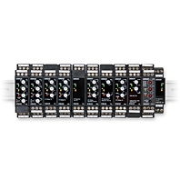
DIN 22.5/17.5 Size Lineup of A Wide Range of Measuring and Monitoring Relays
Related Contents
- Features
- Lineup
- Specifications
- Dimensions
- Catalog / Manual / CAD / Software
last update: December 5, 2013
K8AK-AS Single-phase Current Relay
Input Range
| Model | Range *1 | Connection
terminal |
Setting range | Input
impedance |
Input type | Overload capacity |
|---|---|---|---|---|---|---|
| K8AK-AS1 | 0 to 20 mA
AC/DC |
I1-COM | 2 to 20 mA AC/DC,
10 to 100 mA AC/DC, 50 to 500 mA AC/DC |
Approx. 5 Ω | Direct input | Continuous input at
120% of maximum input 1 s at 150% |
| 0 to 100 mA
AC/DC |
I2-COM | Approx. 1 Ω | Direct input | |||
| 0 to 500 mA
AC/DC |
I3-COM | Approx. 0.2 Ω | Direct input | |||
| K8AK-AS2 | 0 to 1 A
AC/DC |
I1-COM | 0.1 to 1 A AC/DC,
0.5 to 5 A AC/DC, 0.8 to 8 A AC/DC |
Approx. 0.12 Ω
(Load: 0.5 VA) |
Direct input or
commercially available CT |
|
| 0 to 5 A
AC/DC |
I2-COM | Approx. 0.02 Ω
(Load: 1.5 VA) |
||||
| 0 to 8 A
AC/DC |
I3-COM | Approx. 0.02 Ω
(Load: 3 VA) |
--- | |||
| K8AK-AS3 | 0 to 100 A
AC |
I2-COM | 10 to 100 A AC *2,
20 to 200 A AC *2 |
--- | OMRON CT | Continuous input at
120% with an OMRON CT (K8AC-CT200L). 30 s at 200% 1 s at 600% * CT capacity on primary side. |
| 0 to 200 A
AC |
I3-COM | --- | OMRON CT |
*1 The range is selected using connected terminals.
*2 The K8AK-AS3 is designed to be used in combination with an OMRON K8AC-CT200L Current Transformer (CT).
(Direct input is not possible.)
*2 The K8AK-AS3 is designed to be used in combination with an OMRON K8AC-CT200L Current Transformer (CT).
(Direct input is not possible.)
Ratings
| Power supply
voltage |
Isolated power supply | 24 VAC/DC
100 to 240 VAC |
|---|---|---|
| Power consumption | 24 VAC/DC: 2.0 VA/1.1 W max.
100 to 240 VAC: 4.6 VA max. |
|
| Operating value setting range (SV) | 10% to 100% of the maximum value of the setting range
K8AK-AS1: 2 to 20 mA AC/DC 10 to 100 mA AC/DC 50 to 500 mA AC/DC K8AK-AS2: 0.1 to 1 A AC/DC (Compatible with commercially available CTs.) 0.5 to 5 A AC/DC (Compatible with commercially available CTs.) 0.8 to 8 A AC/DC K8AK-AS3: When used with the OMRON CT (K8AC-CT200L). 10 to 100 A AC 20 to 200 A AC |
|
| Operating value | 100% operation at set value | |
| Reset value setting range (HYS.) | 5% to 50% of operating value | |
| Reset method | Manual reset/automatic reset (switchable)
Note: Manual reset: Turn OFF power supply for 1 s or longer. |
|
| Operating time setting range (T) | 0.1 to 30 s | |
| Startup lock time setting range
(LOCK) Note: Enabled only for overcurrent operation. |
0 to 30 s (The startup lock timer starts when the input has reached
approximately 30% or more of the set value.) Note: Enabled only for overcurrent operation. |
|
| Indicators | Power (PWR): Green, Relay output (RY): Yellow, Alarm outputs (ALM): Red | |
| Input impedance | Refer to Input Range on this page. | |
| Output relays | One SPDT relay (NO/NC switched using DIP switch.) | |
| Output relay ratings | Rated load
Resistive load 5 A at 250 VAC 5 A at 30 VDC Maximum contact voltage: 250 VAC or 30 VDC Max. switching current: 5 A Maximum switching capacity: 1,250 VA, 150 W Mechanical life: 10 million operations min. Electrical life: 5 A at 250 VAC or 30 VDC: 50,000 operations 3 A at 250 VAC/30 VDC:100,000 operations |
|
| Ambient operating temperature | -20 to 60°C (with no condensation or icing) | |
| Storage temperature | -25 to 65°C (with no condensation or icing) | |
| Ambient operating humidity | 25% to 85% (with no condensation) | |
| Storage humidity | 25% to 85% (with no condensation) | |
| Altitude | 2,000 m max. | |
| Terminal screw tightening torque | 0.49 N·m | |
| Terminal wiring method | Recommended wire
Solid wire: 2.5 mm2 Twisted wires: AWG16, AWG18 Note: 1. Ferrules with insulating sleeves must be used with twisted wires. 2. Two wires can be twisted together. Recommended ferrules Al 1,5-8BK (for AWG16) manufactured by Phoenix Contact Al 1-8RD (for AWG18) manufactured by Phoenix Contact Al 0,75-8GY (for AWG18) manufactured by Phoenix Contact |
|
| Case color | N1.5 | |
| Case material | PC and ABS | |
| Weight | Approx. 150 g | |
| Mounting | Mounts to DIN Track | |
| Dimensions | 22.5 × 90 × 100 mm (W × H × D) | |
Specifications
| Allowable operating voltage
range |
85% to 110% of power supply voltage | |
|---|---|---|
| Allowable operating
frequency range |
50/60 Hz ±5 Hz | |
| Input frequency range | K8AK-AS1 and K8AK-AS2: DC input or AC input (45 to 65 Hz)
K8AK-AS3: AC input (45 to 65 Hz) |
|
| Overload capacity | K8AK-AS1 and K8AK-AS2: Continuous input at 120% of maximum input, 1 s at 150%
K8AK-AS3: Continuous input at 120%, 30 s at 200%, and 1 s at 600% with an OMRON CT (K8AC-CT200L) Note: Overload capacity of primary side of CT. |
|
| Repeat
error |
Operating value | ±0.5% full scale (at 25°C and 65% humidity, rated power supply voltage, DC or 50/60
Hz sine wave input) |
| Operating time | ±50 ms (at 25°C and 65% humidity, rated power supply voltage) | |
| Applicable
standards |
Conforming
standards |
EN60947-5-1
Installation environment (pollution level 2, installation category III) |
| EMC | EN60947-5-1 | |
| Safety standards | UL 508 (Recognition), Korean Radio Waves Act (Act 10564),
CSA: CAN/CSA C22.2 No.14,CCC: GB14048.5 |
|
| Insulation resistance | 20 MΩ min.
Between external terminals and case Between power supply terminals and input terminals Between power supply terminals and output terminals Between input terminals and output terminals |
|
| Dielectric strength | 2,000 VAC for one minute
Between external terminals and case Between power supply terminals and input terminals Between power supply terminals and output terminals Between input terminals and output terminals |
|
| Noise immunity | 1,500 V power supply terminal common/normal mode
Square-wave noise of ±1 μs/100 ns pulse width with 1-ns rise time |
|
| Vibration resistance | Frequency 10 to 55 Hz, 0.35-mm single amplitude, acceleration 50 m/s2
10 sweeps of 5 min each in X, Y, and Z directions |
|
| Shock resistance | 150 m/s2, 3 times each in 6 directions along 3 axes
Or 100 m/s2 for relay contacts. |
|
| Degree of protection | Terminals: IP20 | |
Relationship of Mounting Distance between K8AK-AS Relays and Input Current (Reference Values)
The following diagram shows the relationship between the mounting distances and the input current. If the relay is used with an input current that exceeds these values, the temperature of the K8AK may rise and shorten the life of the internal components.
K8AK-AW Single-phase Overcurrent/Undercurrent Relays
Input Range
| Model | Range *1 | Connection
terminals |
Setting range | Input
impedance |
Input type | Overload capacity |
|---|---|---|---|---|---|---|
| K8AK-AW1 | 0 to 20 mA
AC/DC |
I1-COM | 2 to 20 mA AC/DC
10 to 100 mA AC/DC 50 to 500 mA AC/DC |
Approx. 5 Ω | Direct input | Continuous input at
120% of maximum input. 1 s at 150% |
| 0 to 100 mA
AC/DC |
I2-COM | Approx. 1 Ω | Direct input | |||
| 0 to 500 mA
AC/DC |
I3-COM | Approx. 0.2 Ω | Direct input | |||
| K8AK-AW2 | 0 to 1 A
AC/DC |
I1-COM | 0.1 to 1 A AC/DC
0.5 to 5 A AC/DC |
Approx. 0.12 Ω
(Load: 0.5 VA) |
Direct input or
commercially available CT |
|
| 0 to 5 A
AC/DC |
I2-COM | Approx. 0.02 Ω
(Load: 1.5 VA) |
||||
| K8AK-AW3 | 0 to 100 A
AC |
I2-COM | 10 to 100 A AC *2
20 to 200 A AC *2 |
--- | OMRON CT | Continuous input at
120% with an OMRON CT (K8AC-CT200L). 30 s at 200% 1 s at 600% * CT capacity on primary side. |
| 0 to 200 A
AC |
I3-COM | --- | OMRON CT |
*1 The range is selected using connected terminals.
*2 The K8AK-AW3 is designed to be used in combination with an OMRON K8AC-CT200L Current Transformer (CT).
(Direct input is not possible.)
*2 The K8AK-AW3 is designed to be used in combination with an OMRON K8AC-CT200L Current Transformer (CT).
(Direct input is not possible.)
Ratings
| Power supply
voltage |
Isolated power supply | 24 VAC/DC
100 to 240 VAC |
|---|---|---|
| Power consumption | 24 VAC/DC: 2.0 VA/1.1 W max.
100 to 240 VAC: 4.6 VA max. |
|
| Operating value setting range (SV) | 10% to 100% of the maximum value of the setting range
K8AK-AW1: 2 to 20 mA AC/DC 10 to 100 mA AC/DC 50 to 500 mA AC/DC K8AK-AW2: 0.1 to 1 A AC/DC (Compatible with commercially available CTs.) 0.5 to 5 A AC/DC (Compatible with commercially available CTs.) K8AK-AW3: When used with the OMRON CT (K8AC-CT200L). 10 to 100 A AC 20 to 200 A AC |
|
| Operating value | 100% operation at set value | |
| Reset value | 5% of operating value (fixed) | |
| Reset method | Manual reset/automatic reset (switchable)
Note: Manual reset: Turn OFF power supply for 1 s or longer. |
|
| Operating time setting range (T) | 0.1 to 30 s | |
| Startup lock time setting range
(LOCK) Note: Enabled only for overcurrent operation. |
0 to 30 s (The startup lock timer starts when the input has reached
approximately 30% or more of the set value.) Note: Enabled only for overcurrent operation. |
|
| Indicators | Power (PWR): Green, Relay output (RY): Yellow, Alarm outputs (ALM): Red | |
| Input impedance | Refer to Input Range on previous page. | |
| Output relays | Two SPDT relay outputs (normally closed operation) | |
| Output relay ratings | Rated load
Resistive load 5 A at 250 VAC 5 A at 30 VDC Maximum contact voltage: 250 VAC or 30 VDC Max. switching current: 5 A Maximum switching capacity: 1,250 VA, 150 W Mechanical life: 10 million operations min. Electrical life: 5 A at 250 VAC or 30 VDC: 50,000 operations 3 A at 250 VAC/30 VDC: 100,000 operations |
|
| Ambient operating temperature | -20 to 60°C (with no condensation or icing) | |
| Storage temperature | -25 to 65°C (with no condensation or icing) | |
| Ambient operating humidity | 25% to 85% (with no condensation) | |
| Storage humidity | 25% to 85% (with no condensation) | |
| Altitude | 2,000 m max. | |
| Terminal screw tightening torque | 0.49 N·m | |
| Terminal wiring method | Recommended wire
Solid wire: 2.5 mm2 Twisted wires: AWG16, AWG18 Note: 1. Ferrules with insulating sleeves must be used with twisted wires. 2. Two wires can be twisted together. Recommended ferrules Al 1,5-8BK (for AWG16) manufactured by Phoenix Contact Al 1-8RD (for AWG18) manufactured by Phoenix Contact Al 0,75-8GY (for AWG18) manufactured by Phoenix Contact |
|
| Case color | N1.5 | |
| Case material | PC and ABS | |
| Weight | Approx. 150 g | |
| Mounting | Mounts to DIN Track. | |
| Dimensions | 22.5 × 90 × 100 mm (W × H × D) | |
Specifications
| Allowable operating voltage
range |
85% to 110% of power supply voltage | |
|---|---|---|
| Allowable operating
frequency range |
50/60 Hz ±5 Hz | |
| Input frequency range | K8AK-AW1 and K8AK-AW2: DC input or AC input (45 to 65 Hz)
K8AK-AW3: AC input (45 to 65 Hz) |
|
| Overload capacity | K8AK-AW1 and K8AK-AW2: Continuous input at 120% of maximum input, 1 s at 150%
K8AK-AW3: Continuous input at 120%, 30 s at 200%, and 1 s at 600% with an OMRON CT (K8AC-CT200L). Note: CT capacity on primary side. |
|
| Repeat
accuracy |
Operating value | ±0.5% full scale (at 25°C and 65% humidity, rated power supply voltage, DC or 50/60
Hz sine wave input) |
| Operating time | ±50 ms (at 25°C and 65% humidity, rated power supply voltage) | |
| Applicable
standards |
Conforming
standards |
EN60947-5-1
Installation environment (pollution level 2, installation category III) |
| EMC | EN60947-5-1 | |
| Safety standards | UL 508 (Recognition), Korean Radio Waves Act (Act 10564),
CSA: CAN/CSA C22.2 No.14,CCC: GB14048.5 |
|
| Insulation resistance | 20 MΩ min.
Between external terminals and case Between power supply terminals and input terminals Between power supply terminals and output terminals Between input terminals and output terminals |
|
| Dielectric strength | 2,000 VAC for one minute
Between external terminals and case Between power supply terminals and input terminals Between power supply terminals and output terminals Between input terminals and output terminals |
|
| Noise immunity | 1,500 V power supply terminal common/normal mode
Square-wave noise of ±1 μs/100 ns pulse width with 1-ns rise time |
|
| Vibration resistance | Frequency: 10 to 55 Hz, acceleration 50 m/s2
10 sweeps of 5 min each in X,Y, and Z directions |
|
| Shock resistance | 150 m/s2, 3 times each in 6 directions along 3 axes
Or 100 m/s2 for relay contacts. |
|
| Degree of protection | Terminals: IP20 | |
Relationship of Mounting Distance between K8AK-AW Relays and Input Current (Reference Values)
The following diagram shows the relationship between the mounting distances and the input current.
If the relay is used with an input current that exceeds these values, the temperature of the K8AK may rise and shorten the life of the internal components.
K8AK-VS Single-phase Voltage Relay
Input Range
| Model | Range * | Connection
terminal |
Setting range | Input
impedance |
Overload capacity |
|---|---|---|---|---|---|
| K8AK-VS2 | 0 to 10 V AC/DC | V1-COM | 1 to 10 V AC/DC,
3 to 30 V AC/DC, 15 to 150 V AC/DC |
Approx. 120 kΩ | Continuous input at 115%
of maximum input 10 s at 125% (up to 600 VAC) |
| 0 to 30 V AC/DC | V2-COM | Approx. 320 kΩ | |||
| 0 to 150 V AC/DC | V3-COM | Approx. 1.6 MΩ | |||
| K8AK-VS3 | 0 to 200 V AC/DC | V1-COM | 20 to 200 V AC/DC,
30 to 300 V AC/DC, 60 to 600 V AC/DC |
Approx. 1.2 MΩ | |
| 0 to 300 V AC/DC | V2-COM | Approx. 1.7 MΩ | |||
| 0 to 600 V AC/DC | V3-COM | Approx. 3.1 MΩ |
* The range is selected using connected terminals.
Ratings
| Power supply
voltage |
Isolated power supply | 24 VAC/DC
100 to 240 VAC |
|---|---|---|
| Power consumption | 24 VAC/DC: 2.0 VA/1.1 W max.
100 to 240 VAC: 4.6 VA max. |
|
| Operating value setting range (SV) | 10% to 100% of maximum setting range
K8AK-VS2: 1 to 10 V AC/DC 3 to 30 V AC/DC 15 to 150 V AC/DC K8AK-VS3: 20 to 200 V AC/DC 30 to 300 V AC/DC 60 to 600 V AC/DC |
|
| Operating value | 100% operation at set value | |
| Reset value setting range (HYS.) | 5% to 50% of operating value | |
| Reset method | Manual reset/automatic reset (switchable)
Note: Manual reset: Turn OFF power supply for 1 s or longer. |
|
| Operating time setting range (T) | 0.1 to 30 s | |
| Power ON lock time (LOCK) | 1 s or 5 s (Switched using DIP switch.) | |
| Indicators | Power (PWR): Green, Relay output (RY): Yellow, Alarm outputs (ALM): Red | |
| Input impedance | Refer to Input Range on previous page. | |
| Output relays | One SPDT relay (NO/NC switched using DIP switch.) | |
| Output relay ratings | Rated load
Resistive load 5 A at 250 VAC 5 A at 30 VDC Maximum contact voltage: 250 VAC or 30 VDC Max. switching current: 5 A Maximum switching capacity: 1,250 VA, 150 W Mechanical life: 10 million operations min. Electrical life: 5 A at 250 VAC or 30 VDC: 50,000 operations 3 A at 250 VAC or 30 VDC: 100,000 operations |
|
| Ambient operating temperature | -20 to 60°C (with no condensation or icing) | |
| Storage temperature | -25 to 65°C (with no condensation or icing) | |
| Ambient operating humidity | 25% to 85% (with no condensation) | |
| Storage humidity | 25% to 85% (with no condensation) | |
| Altitude | 2,000 m max. | |
| Terminal screw tightening torque | 0.49 N·m | |
| Terminal wiring method | Recommended wire
Solid wire: 2.5 mm2 Twisted wires: AWG16, AWG18 Note: 1. Ferrules with insulating sleeves must be used with twisted wires. 2. Two wires can be twisted together. Recommended ferrules Al 1,5-8BK (for AWG16) manufactured by Phoenix Contact Al 1-8RD (for AWG18) manufactured by Phoenix Contact Al 0,75-8GY (for AWG18) manufactured by Phoenix Contact |
|
| Case color | N1.5 | |
| Case material | PC and ABS | |
| Weight | Approx. 150 g | |
| Mounting | Mounts to DIN Track. | |
| Dimensions | 22.5 × 90 × 100 mm (W × H × D) | |
Specifications
| Allowable operating voltage range | 85% to 110% of rated power supply voltage | |
|---|---|---|
| Allowable operating frequency range | 50/60 Hz ±5 Hz | |
| Input frequency | 40 to 500 Hz | |
| Overload capacity | Continuous input at 115% of maximum input, 10 s at 125% (up to 600 VAC). | |
| Repeat
accuracy |
Operating value | ±0.5% full scale (at 25°C and 65% humidity, rated power supply voltage, DC
or 50/60 Hz sine wave input) |
| Operating time | ±50 ms (at 25°C and 65% humidity, rated power supply voltage) | |
| Applicable
standards |
Conforming standards | EN60947-5-1
Installation environment (pollution level 2, installation category III) |
| EMC | EN60947-5-1 | |
| Safety standards | UL 508 (Recognition), Korean Radio Waves Act (Act 10564),
CSA: CAN/CSA C22.2 No.14, CCC: GB14048.5 |
|
| Insulation resistance | 20 MΩ min.
Between external terminals and case Between power supply terminals and input terminals Between power supply terminals and output terminals Between input terminals and output terminals |
|
| Dielectric strength | 2,000 VAC for one minute
Between external terminals and case Between power supply terminals and input terminals Between power supply terminals and output terminals Between input terminals and output terminals |
|
| Noise immunity | 1,500 V power supply terminal common/normal mode
Square-wave noise of ±1 μs/100 ns pulse width with 1-ns rise time |
|
| Vibration resistance | Frequency: 10 to 55 Hz, acceleration 50 m/s2
10 sweeps of 5 min each in X,Y, and Z directions |
|
| Shock resistance | 150 m/s2 3 times each in 6 directions along 3 axes.
Or 100 m/s2 for relay contacts. |
|
| Degree of protection | Terminals: IP20 | |
K8AK-VW Single-phase Overvoltage/Undervoltage Relays
Input Range
| Model | Range * | Connection
terminal |
Setting range | Input
impedance |
Overload capacity |
|---|---|---|---|---|---|
| K8AK-VW2 | 0 to 10 V AC/DC | V1-COM | 1 to 10 V AC/DC
3 to 30 V AC/DC 15 to 150 V AC/DC |
Approx. 120 kΩ | Continuous input at 115% of
maximum input. 10 s at 125% (up to 600 VAC) |
| 0 to 30 V AC/DC | V2-COM | Approx. 320 kΩ | |||
| 0 to 150 V AC/DC | V3-COM | Approx. 1.6 MΩ | |||
| K8AK-VW3 | 0 to 200 V AC/DC | V1-COM | 20 to 200 V AC/DC
30 to 300 V AC/DC 60 to 600 V AC/DC |
Approx. 1.2 MΩ | |
| 0 to 300 V AC/DC | V2-COM | Approx. 1.7 MΩ | |||
| 0 to 600 V AC/DC | V3-COM | Approx. 3.1 MΩ |
* The range is selected using connected terminals.
Ratings
| Power supply
voltage |
Isolated power supply | 24 VAC/DC
100 to 240 VAC |
|---|---|---|
| Power consumption | 24 VAC/DC: 2.0 VA/1.1 W max.
100 to 240 VAC: 4.6 VA max. |
|
| Operating value setting range
(AL1 and AL2) |
10% to 100% of the maximum value of the setting range
K8AK-VW2: 1 to 10 V AC/DC 3 to 30 V AC/DC 15 to 150 V AC/DC K8AK-VW3: 20 to 200 V AC/DC 30 to 300 V AC/DC 60 to 600 V AC/DC |
|
| Operating value | 100% operation at set value | |
| Reset value | 5% of operating value (fixed) | |
| Reset method | Manual reset/automatic reset (switchable)
Note: Manual reset: Turn OFF power supply for 1 s or longer. |
|
| Operating time setting range (T) | 0.1 to 30 s | |
| Power ON lock time (LOCK) | 1 s or 5 s (Switched using DIP switch.) | |
| Indicators | Power (PWR): Green, Relay output (RY): Yellow, Alarm outputs (AL1, AL2): Red | |
| Input impedance | Refer to Input Range on previous page. | |
| Output relays | Two SPDT relays (NC operation) | |
| Output relay ratings | Rated load
Resistive load 5 A at 250 VAC 5 A at 30 VDC Maximum contact voltage: 250 VAC or 30 VDC Max. switching current: 5 A Maximum switching capacity: 1,250 VA, 150 W Mechanical life: 10 million operations min. Electrical life: 5 A at 250 VAC or 30 VDC: 50,000 operations 3 A at 250 VAC or 30 VDC: 100,000 operations |
|
| Ambient operating temperature | -20 to 60°C (with no condensation or icing) | |
| Storage temperature | -25 to 65°C (with no condensation or icing) | |
| Ambient operating humidity | 25% to 85% (with no condensation) | |
| Storage humidity | 25% to 85% (with no condensation) | |
| Altitude | 2,000 m max. | |
| Terminal screw tightening torque | 0.49 N·m | |
| Terminal wiring method | Solid wire: 2.5 mm2
Twisted wires: AWG16, AWG18 Note: 1. Ferrules with insulating sleeves must be used with twisted wires. 2. Two wires can be twisted together. Recommended ferrules Al 1,5-8BK (for AWG16) manufactured by Phoenix Contact Al 1-8RD (for AWG18) manufactured by Phoenix Contact Al 0,75-8GY (for AWG18) manufactured by Phoenix Contact |
|
| Case color | N1.5 | |
| Case material | PC and ABS | |
| Weight | Approx. 150 g | |
| Mounting | Mounts to DIN Track. | |
| Dimensions | 22.5 × 90 × 100 mm (W × H × D) | |
Specifications
| Allowable operating voltage range | 85% to 110% of rated power supply voltage | |
|---|---|---|
| Allowable operating frequency range | 50/60 Hz ±5 Hz | |
| Input frequency range | 40 to 500 Hz | |
| Overload capacity | Continuous input at 115% of maximum input, 10 s at 125% (up to 600 VAC). | |
| Repeat error | Operating value | ±0.5% full scale (at 25°C and an ambient humidity of 65% at the rated
power supply voltage, DC and 50/60 Hz sine wave input) |
| Operating time | ±50 ms (at 25°C and 65% humidity, rated power supply voltage) | |
| Applicable
standards |
Conforming standards | EN60947-5-1
Installation environment (pollution level 2, installation category III) |
| EMC | EN60947-5-1 | |
| Safety standards | UL 508 (Recognition), Korean Radio Waves Act (Act 10564),
CSA: CAN/CSA C22.2 No.14, CCC: GB14048.5 |
|
| Insulation resistance | 20 MΩ min.
Between all external terminals and the case Between all power supply terminals and all input terminals Between all power supply terminals and all output terminals Between all input terminals and all output terminals |
|
| Dielectric strength | 2,000 VAC for 1 min
Between all external terminals and the case Between all power supply terminals and all input terminals Between all power supply terminals and all output terminals Between all input terminals and all output terminals |
|
| Noise immunity | 1,500 V power supply terminal common/normal mode
Square-wave noise of ±1 μs/100 ns pulse width with 1-ns rise time |
|
| Vibration resistance | Frequency: 10 to 55 Hz, acceleration 50 m/s2
10 sweeps of 5 min each in X,Y, and Z directions |
|
| Shock resistance | 150 m/s2 3 times each in 6 directions along 3 axes.
Or 100 m/s2 for relay contacts. |
|
| Degree of protection | Terminals: IP20 | |
K8DS-PH Phase-sequence Phase-loss Relay
Ratings
| Rated input voltage | 3-phase, 200 to 480 VAC (3-wire) |
|---|---|
| Input load | Approx. 2.7 VA |
| Reversed phase and phase loss operating time | 0.1 s max. |
| Reset method | Automatic reset |
| Indicators | Power (PWR): Green, Relay output (RY): Yellow |
| Output relays | One SPDT relay (NC operation) |
| Output relay ratings | Rated load
Resistive load 5 A at 250 VAC 5 A at 30 VDC Max. switching voltage 250 VAC or 30 VDC Max. switching current: 5 A Maximum switching capacity: 1,250 VA, 150 W Mechanical life: 10 million operations min. Electrical life: 5 A at 250 VAC or 30 VDC:50,000 operations 3 A at 250 VAC/30 VDC:100,000 operations |
| Ambient operating temperature | -20 to 60°C (with no condensation or icing) |
| Storage temperature | -25 to 65°C (with no condensation or icing) |
| Ambient operating humidity | 25% to 85% (with no condensation) |
| Storage humidity | 25% to 85% (with no condensation) |
| Altitude | 2,000 m max. |
| Terminal screw tightening torque | 0.49 N·m |
| Terminal wiring method | Recommended wire
Solid wire: 2.5 mm2 Twisted wires: AWG16, AWG18 Note: 1. Ferrules with insulating sleeves must be used with twisted wires. 2. Two wires can be twisted together. Recommended ferrules Al 1,5-8BK (for AWG16) manufactured by Phoenix Contact Al 1-8RD (for AWG18) manufactured by Phoenix Contact Al 0,75-8GY (for AWG18) manufactured by Phoenix Contact |
| Case color | N1.5 |
| Case material | PC and ABS |
| Weight | Approx. 60 g |
| Mounting | Mounts to DIN Track. |
| Dimensions | 17.5 × 80 × 73 mm (W × D × H) |
Specifications
| Input voltage range | 200 to 480 VAC | |
|---|---|---|
| Input frequency | 50/60 Hz (no presumed range) | |
| Overload capacity | Continuous 500 V | |
| Applicable
standards |
Conforming standards | EN60947-5-1
Installation environment (pollution level 2, installation category III) |
| EMC | EN60947-5-1 | |
| Safety standards | UL 508 (Recognition), Korean Radio Waves Act (Act 10564),
CSA: CAN/CSA C22.2 No.14, CCC: GB14048.5 |
|
| Insulation resistance | 20 MΩ min.
Between external terminals and case Between input terminals and output terminals |
|
| Dielectric strength | 2,000 VAC for one minute
Between external terminals and case Between input terminals and output terminals |
|
| Noise immunity | 1,500 V power supply terminal common/normal mode
Square-wave noise of ±1 μs/100 ns pulse width with 1-ns rise time |
|
| Vibration resistance | Frequency: 10 to 55 Hz, acceleration 50 m/s2
10 sweeps of 5 min each in X,Y, and Z directions |
|
| Shock resistance | 150 m/s2, 3 times each in 6 directions along 3 axes
However, 100 m/s2 for relay contacts. |
|
| Degree of protection | Terminals: IP20 | |
Relationship of Mounting Distance between K8DS-PH Relays and Ambient Temperature (Reference Values)
The following diagram shows the relationship between the mounting distances and the ambient temperature.
If the relay is used with an ambient temperature that exceeds these values, the temperature of the K8DS may rise and shorten the life of the internal components.
K8AK-PH Phase-sequence Phase-loss Relay
Ratings
| Rated input voltage | 3-phase, 200 to 480 VAC (3-wire) |
|---|---|
| Input load | Approx. 4.1 VA |
| Reversed phase and phase loss operating time | 0.1 s max. |
| Reset method | Automatic reset |
| Indicators | Power (PWR): Green, Relay output (RY): Yellow |
| Output relays | One DPDT relay (NC operation) |
| Output relay ratings | Rated load
Resistive load 5 A at 250 VAC 5 A at 30 VDC Max. switching voltage 250 VAC or 30 VDC Max. switching current: 5 A Minimum load: 24 VDC, 40 mA Mechanical life: 10 million operations min. Electrical life: 5 A at 250 VAC or 30 VDC: 50,000 operations 3 A at 250 VAC/30 VDC:100,000 operations |
| Ambient operating temperature | -20 to 60°C (with no condensation or icing) |
| Storage temperature | -25 to 65°C (with no condensation or icing) |
| Ambient operating humidity | 25% to 85% (with no condensation) |
| Storage humidity | 25% to 85% (with no condensation) |
| Altitude | 2,000 m max. |
| Terminal screw tightening torque | 0.49 N·m |
| Terminal wiring method | Recommended wire
Solid wire: 2.5 mm2 Twisted wires: AWG16, AWG18 Note: 1. Ferrules with insulating sleeves must be used with twisted wires. 2. Two wires can be twisted together. Recommended ferrules Al 1,5-8BK (for AWG16) manufactured by Phoenix Contact Al 1-8RD (for AWG18) manufactured by Phoenix Contact Al 0,75-8GY (for AWG18) manufactured by Phoenix Contact |
| Case color | N1.5 |
| Case material | PC and ABS |
| Weight | Approx. 130 g |
| Mounting | Mounts to DIN Track. |
| Dimensions | 22.5 × 90 × 100 mm (W × H × D) |
Specifications
| Input voltage range | 200 to 480 VAC | |
|---|---|---|
| Input frequency | 50/60 Hz (no presumed range) | |
| Overload capacity | Continuous 528 V | |
| Applicable
standards |
Conforming standards | EN60947-5-1
Installation environment (pollution level 2, installation category III) |
| EMC | EN60947-5-1 | |
| Safety standards | UL 508 (Recognition), Korean Radio Waves Act (Act 10564),
CSA: CAN/CSA C22.2 No.14, CCC: GB14048.5 |
|
| Insulation resistance | 20 MΩ min.
Between external terminals and case Between input terminals and output terminals |
|
| Dielectric strength | 2,000 VAC for one minute
Between external terminals and case Between input terminals and output terminals |
|
| Noise immunity | 1,500 V power supply terminal common/normal mode
Square-wave noise of ±1 μs/100 ns pulse width with 1-ns rise time |
|
| Vibration resistance | Frequency: 10 to 55 Hz, acceleration 50 m/s2
10 sweeps of 5 min each in X,Y, and Z directions |
|
| Shock resistance | 150 m/s2, 3 times each in 6 directions along 3 axes
However, 100 m/s2 for relay contacts. |
|
| Degree of protection | Terminals: IP20 | |
Relationship of Mounting Distance between K8AK-PH Relays and Ambient Temperature (Reference Values)
The following diagram shows the relationship between the mounting distances and the ambient temperature.
If the relay is used with an ambient temperature that exceeds these values, the temperature of the K8AK may rise and shorten the life of the internal components.
K8AK-PW Three-phase Voltage Relay
Ratings
| Rated input voltage | K8AK-PW1 | Three-phase, three-wire Mode: 200, 220, 230 and 240 VAC
Three-phase, four-wire Mode: 115, 127, 133 and 138 VAC |
|---|---|---|
| K8AK-PW2 | Three-phase, three-wire Mode: 380, 400, 415 and 480 VAC
Three-phase, four-wire Mode: 220, 230, 240 and 277 VAC |
|
| Input load | K8AK-PW1: Approx. 4.4 VA
K8AK-PW2: Approx. 4.4 VA |
|
| Operating value setting range (OVER, UNDER) | Overvoltage
-30% to 25% of rated input voltage Undervoltage -30% to 25% of rated input voltage Note: The rated input voltage can be switched using the DIP switch. |
|
| Operating value | 100% operation at set value | |
| Reset value | 5% of operating value (fixed) | |
| Reset method | Automatic reset | |
| Operating time setting range (T) | Overvoltage and undervoltage: 0.1 to 30 s | |
| Startup lock time (LOCK) | 1 s/5 s (Changed with the DIP switch.) | |
| Indicators | Power (PWR): Green, Relay output (RY): Yellow, OVER/UNDER: Red | |
| Output relays | Two SPDT relays (NC operation) | |
| Output relay ratings | Rated load
Resistive load 5 A at 250 VAC 5 A at 30 VDC Maximum contact voltage: 250 VAC or 30 VDC Max. switching current: 5 A Maximum switching capacity: 1,250 VA, 150 W Mechanical life: 10 million operations min. Electrical life: 5 A at 250 VAC or 30 VDC:50,000 operations 3 A at 250 VAC/30 VDC:100,000 operations |
|
| Ambient operating temperature | -20 to 60°C (with no condensation or icing) | |
| Storage temperature | -25 to 65°C (with no condensation or icing) | |
| Ambient operating humidity | 25% to 85% (with no condensation) | |
| Storage humidity | 25% to 85% (with no condensation) | |
| Altitude | 2,000 m max. | |
| Terminal screw tightening torque | 0.49 N·m | |
| Terminal wiring method | Recommended wire
Solid wire: 2.5 mm2 Twisted wires: AWG16, AWG18 Note: 1. Ferrules with insulating sleeves must be used with twisted wires. 2. Two wires can be twisted together. Recommended ferrules Al 1,5-8BK (for AWG16) manufactured by Phoenix Contact Al 1-8RD (for AWG18) manufactured by Phoenix Contact Al 0,75-8GY (for AWG18) manufactured by Phoenix Contact |
|
| Case color | N1.5 | |
| Case material | PC and ABS | |
| Weight | Approx. 150 g | |
| Mounting | Mounts to DIN Track. | |
| Dimensions | 22.5 × 90 × 100 mm (W × H × D) | |
Specifications
| Input frequency range | 50/60 Hz | |
|---|---|---|
| Overload capacity | Continuous input at 115% of maximum input. 10 s at 125%. (up to 600 VAC) | |
| Repeat
accuracy |
Operating value | ±0.5% full scale (at 25°C and an ambient humidity of 65% at the rated power
supply voltage, DC and 50/60 Hz sine wave input) |
| Operating time | ±50 ms (at 25°C and 65% humidity, rated power supply voltage) | |
| Applicable
standards |
Conforming standards | EN60947-5-1
Installation environment (pollution level 2, installation category III) |
| EMC | EN60947-5-1 | |
| Safety standards | UL 508 (Recognition), Korean Radio Waves Act (Act 10564),
CSA: CAN/CSA C22.2 No.14, CCC: GB14048.5 |
|
| Insulation resistance | 20 MΩ
Between all external terminals and the case Between all input terminals and all output terminals |
|
| Dielectric strength | 2,000 VAC for 1 min
Between all external terminals and the case Between all input terminals and all output terminals |
|
| Noise immunity | 1,500 V power supply terminal common/normal mode
Square-wave noise of ±1 μs/100 ns pulse width with 1-ns rise time |
|
| Vibration resistance | Frequency: 10 to 55 Hz, acceleration 50 m/s2
10 sweeps of 5 min each in X,Y, and Z directions |
|
| Shock resistance | 150 m/s2, 3 times each in 6 directions along 3 axes
However, 100 m/s2 for relay contacts. |
|
| Degree of protection | Terminals: IP20 | |
Relationship of Mounting Distance between K8AK-PW Relays and Ambient Temperature (Reference Values)
The following diagram shows the relationship between the mounting distances and the ambient temperature.
If the relay is used with an ambient temperature that exceeds these values, the temperature of the K8AK may rise and shorten the life of the internal components.
K8AK-PM Three-phase Phase-sequence Phase-loss Relay
Ratings
| Rated input
voltage |
K8AK-PM1 | Three-phase, three-wire Mode: 200, 220, 230 and 240 VAC
Three-phase, four-wire Mode: 115, 127, 133 and 138 VAC |
|---|---|---|
| K8AK-PM2 | Three-phase, three-wire Mode: 380, 400, 415 and 480 VAC
Three-phase, four-wire Mode: 220, 230, 240 and 277 VAC |
|
| Input load | K8AK-PM1: Approx. 4.4 VA
K8AK-PM2: Approx. 4.4 VA |
|
| Operating value setting range (OVER, UNDER) | Overvoltage
-30% to 25% of rated input voltage Undervoltage -30% to 25% of rated input voltage Note: The rated input voltage can be switched using the DIP switch. |
|
| Operating value | 100% operation at set value | |
| Reset value | 5% of operating value (fixed) | |
| Reset method | Automatic reset | |
| Operating time
setting range (T) |
Overvoltage/undervoltage | 0.1 to 30 s |
| Reversed phase/phase loss | 0.1 s | |
| Startup lock time (LOCK) | 1 s or 5 s (Switched using DIP switch.) | |
| Indicators | Power (PWR): Green, Relay output (RY): Yellow, OVER/UNDER: Red | |
| Output relays | Two SPDT relays (NC operation) | |
| Output relay ratings | Rated load
Resistive load 5 A at 250 VAC 5 A at 30 VDC Maximum contact voltage: 250 VAC or 30 VDC Max. switching current: 5 A Maximum switching capacity: 1,250 VA, 150 W Mechanical life: 10 million operations min. Electrical life: 5 A at 250 VAC or 30 VDC: 50,000 operations 3 A at 250 VAC/30 VDC: 100,000 operations |
|
| Ambient operating temperature | -20 to 60°C (with no condensation or icing) | |
| Storage temperature | -25 to 65°C (with no condensation or icing) | |
| Ambient operating humidity | 25% to 85% (with no condensation) | |
| Storage humidity | 25% to 85% (with no condensation) | |
| Altitude | 2,000 m max. | |
| Terminal screw tightening torque | 0.49 N·m | |
| Terminal wiring method | Recommended wire
Solid wire: 2.5 mm2 Twisted wires: AWG16, AWG18 Note: 1. Ferrules with insulating sleeves must be used with twisted wires. 2. Two wires can be twisted together. Recommended ferrules Al 1,5-8BK (for AWG16) manufactured by Phoenix Contact Al 1-8RD (for AWG18) manufactured by Phoenix Contact Al 0,75-8GY (for AWG18) manufactured by Phoenix Contact |
|
| Case color | N1.5 | |
| Case material | PC and ABS | |
| Weight | Approx. 150 g | |
| Mounting | Mounts to DIN Track. | |
| Dimensions | 22.5 × 90 × 100 mm (W × H × D) | |
Specifications
| Input frequency | 50/60 Hz | |
|---|---|---|
| Overload capacity | Continuous input at 115% of maximum input, 10 s at 125% (up to 600 VAC). | |
| Repeat
accuracy |
Operating value | ±0.5% full scale (at 25°C and an ambient humidity of 65% at the rated power
supply voltage, DC and 50/60 Hz sine wave input) |
| Operating time | ±50 ms (at 25°C and 65% humidity, rated power supply voltage) | |
| Applicable
standards |
Conforming standards | EN60947-5-1
Installation environment (pollution level 2, installation category III) |
| EMC | EN60947-5-1 | |
| Safety standards | UL 508 (Recognition), Korean Radio Waves Act (Act 10564),
CSA: CAN/CSA C22.2 No.14, CCC: GB14048.5 |
|
| Insulation resistance | 20 MΩ
Between all external terminals and the case Between all input terminals and all output terminals |
|
| Dielectric strength | 2,000 VAC for 1 min
Between all external terminals and the case Between all input terminals and all output terminals |
|
| Noise immunity | 1,500 V power supply terminal common/normal mode
Square-wave noise of ±1 μs/100 ns pulse width with 1-ns rise time |
|
| Vibration resistance | Frequency: 10 to 55 Hz, acceleration 50 m/s2
10 sweeps of 5 min each in X,Y, and Z directions |
|
| Shock resistance | 150 m/s2, 3 times each in 6 directions along 3 axes
However, 100 m/s2 for relay contacts. |
|
| Degree of protection | Terminals: IP20 | |
Relationship of Mounting Distance between K8AK-PM Relays and Ambient Temperature (Reference Values)
The following diagram shows the relationship between the mounting distances and the ambient temperature.
If the relay is used with an ambient temperature that exceeds these values, the temperature of the K8AK may rise and shorten the life of the internal components.
K8AK-PA Three-phase Asymmetry and Phase-sequence Phase-loss Relay
Ratings
| Rated input
voltage |
K8AK-PA1 | Three-phase, three-wire Mode: 200, 220, 230 and 240 VAC
Three-phase, four-wire Mode: 115, 127, 133 and 138 VAC |
|---|---|---|
| K8AK-PA2 | Three-phase, three-wire Mode: 380, 400, 415 and 480 VAC
Three-phase, four-wire Mode: 220, 230, 240 and 277 VAC |
|
| Input load | K8AK-PA1: Approx. 4.4 VA
K8AK-PA2: Approx. 4.4 VA |
|
| Operating value setting range (ASY.) | Asymmetry set value: 2% to 22% | |
| Operating value | Asymmetry operating value = Rated input voltage × Asymmetry set value (%)
The asymmetry operation will function when the potential difference between the highest and lowest voltage phases equals or exceeds the asymmetry operating value. |
|
| Reset value setting range (HYS.) | 5% of operating value (fixed) | |
| Reset method | Automatic reset | |
| Operating time
setting range (T) |
Asymmetry | 0.1 to 30 s |
| Reversed phase/
phase loss |
0.1 s | |
| Startup lock time (LOCK) | 1 s/5 s (Changed with the DIP switch.) | |
| Indicators | Power (PWR): Green, Relay output (RY): Yellow, Alarm outputs (ALM): Red | |
| Output relays | One SPDT relay (NC operation) | |
| Output relay ratings | Rated load
Resistive load 5 A at 250 VAC 5 A at 30 VDC Maximum contact voltage: 250 VAC or 30 VDC Max. switching current: 5 A Maximum switching capacity: 1,250 VA, 150 W Mechanical life: 10 million operations min. Electrical life: 5 A at 250 VAC or 30 VDC: 50,000 operations 3 A at 250 VAC/30 VDC: 100,000 operations |
|
| Ambient operating temperature | -20 to 60°C (with no condensation or icing) | |
| Storage temperature | -25 to 65°C (with no condensation or icing) | |
| Ambient operating humidity | 25% to 85% (with no condensation) | |
| Storage humidity | 25% to 85% (with no condensation) | |
| Altitude | 2,000 m max. | |
| Terminal screw tightening torque | 0.49 Nm | |
| Terminal wiring method | Recommended wire
Solid wire: 2.5 mm2 Twisted wires: AWG16, AWG18 Note: 1. Ferrules with insulating sleeves must be used with twisted wires. 2. Two wires can be twisted together. Recommended ferrules Al 1,5-8BK (for AWG16) manufactured by Phoenix Contact Al 1-8RD (for AWG18) manufactured by Phoenix Contact Al 0,75-8GY (for AWG18) manufactured by Phoenix Contact |
|
| Case color | N1.5 | |
| Case material | PC and ABS | |
| Weight | Approx. 130 g | |
| Mounting | Mounts to DIN Track. | |
| Dimensions | 22.5 × 90 × 100 mm (W × H × D) | |
Specifications
| Input frequency | 50/60 Hz | |
|---|---|---|
| Overload capacity | Continuous input at 115% of maximum input, 10 s at 125% (up to 600 VAC). | |
| Repeat
accuracy |
Operating value | ±0.5% full scale (at 25°C and 65% humidity, rated power supply voltage, 50/60
Hz sine wave input) |
| Operating time | ±50 ms (at 25°C and 65% humidity, rated power supply voltage) | |
| Applicable
standards |
Conforming standards | EN60947-5-1
Installation environment (pollution level 2, installation category III) |
| EMC | EN60947-5-1 | |
| Safety standards | UL 508 (Recognition), Korean Radio Waves Act (Act 10564),
CSA: CAN/CSA C22.2 No.14, CCC: GB14048.5 |
|
| Insulation resistance | 20 MΩ min.
Between external terminals and case Between input terminals and output terminals |
|
| Dielectric strength | 2,000 VAC for one minute
Between external terminals and case Between input terminals and output terminals |
|
| Noise immunity | 1,500 V power supply terminal common/normal mode
Square-wave noise of ±1 μs/100 ns pulse width with 1-ns rise time |
|
| Vibration resistance | Frequency: 10 to 55 Hz, acceleration 50 m/s2
10 sweeps of 5 min each in X,Y, and Z directions |
|
| Shock resistance | 150 m/s2, 3 times each in 6 directions along 3 axes
However, 100 m/s2 for relay contacts. |
|
| Degree of protection | Terminals: IP20 | |
Relationship of Mounting Distance between K8AK-PA Relays and Ambient Temperature (Reference Values)
The following diagram shows the relationship between the mounting distances and the ambient temperature.
If the relay is used with an ambient temperature that exceeds these values, the temperature of the K8AK may rise and shorten the life of the internal components.
K8AK-TH Temperature Monitoring Relay
Ratings
| Power supply voltage | 100 to 240 VAC 50/60 Hz | 24 VAC 50/60 Hz or 24 VDC | |
|---|---|---|---|
| Allowable voltage range | 85% to 110% of power supply voltage | ||
| Power consumption | 5 VA max. | 2 W max. (24 VDC), 4 VA max. (24 VAC) | |
| Sensor inputs | K8AK-TH11S | Thermocouple: K, J, T, E; Platinum-resistance thermometer: Pt100, Pt1000 | |
| K8AK-TH12S | Thermocouple: K, J, T, E, B, R, S, PLII | ||
| Output relay | One SPDT relay (5 A at 250 VAC, resistive load) | ||
| External inputs
(for latch setting) |
Contact input | ON: 1 kΩ max., OFF: 100 kΩ min. | |
| Non-contact input | ON residual voltage: 1.5 V max., OFF leakage current: 0.1 mA max. | ||
| Leakage current: Approx. 10 mA | |||
| Setting method | Rotary switch setting (set of three switches) | ||
| Indicators | Power (PWR): Green LED, Relay output (ALM): Red LED | ||
| Other functions | Alarm Mode (upper limit/lower limit), non-fail safe/fail safe selection, output
latch, setting protection, temperature unit °C/°F |
||
| Ambient operating temperature | -20 to 55°C (with no condensation or icing) | ||
| Ambient operating humidity | Relative humidity: 25% to 85% | ||
| Storage temperature | -25 to 65°C (with no condensation or icing) | ||
Characteristics
| Measurement accuracy | ±1% of the setting range | |
|---|---|---|
| hysteresis width | 2°C | |
| Output relay | 1 SPDT relay output
5 A at 250 VAC or 30 VDC (resistive load) Electrical life: 50,000 operations. 3 A at 250 VAC or 30 VDC (resistive load) Electrical life: 100,000 operations |
|
| Sampling cycle | 100 ms | |
| Insulation resistance | 20 MΩ (at 500 V) between charged terminals and exposed uncharged parts
20 MΩ (at 500 V) between any charged terminals (i.e., between input, output, and power supply terminals) 20 MΩ (at 500 V) between contacts (open) |
|
| Dielectric strength | 2,300 VAC, 50/60 Hz for 1 min between terminals of different charge | |
| Vibration resistance | Vibration of 10 to 55 Hz and acceleration of 50 m/s2 for 5 min with 10 sweeps each in X, Y,
and Z directions |
|
| Shock resistance | 150 m/s2 (100 m/s2 for relay contacts) 3 times each in 6 directions in X, Y, and Z directions | |
| Weight | Approx. 160 g | |
| Degree of protection | IP20 | |
| Memory protection | Non-volatile memory (number of writes: 1 million) | |
| Safety
Standards |
Approved
standards |
UL 61010-1
Installation environment (pollution level 2, installation category II) |
| EMC | EN 61326-1 | |
| Application
standards |
UL 61010-1, Korean Radio Waves Act (Act 10564), CSA: CAN/CSA C22.2 No.14,
CCC: GB14048.5 |
|
| Terminal screw
tightening torque |
0.49 N·m | |
| Crimp terminals | Two solid wires of 2.5 mm2 or two ferrules of 1.5 mm2 with insulation sleeves can be
tightened together. |
|
| Case color | N1.5 | |
| Case material | PC and ABS | |
| Mounting | Mounts to DIN Track. | |
| Dimensions | 22.5 × 100 × 90 mm (W × D × H) | |
Setting Ranges
K8AK-TH11S
Centigrade
Fahrenheit
K8AK-TH12S
Centigrade
Fahrenheit
Temperature Input Range
| TH11S | °C | °F | ||
|---|---|---|---|---|
| Input type | Lower limit | Upper limit | Lower limit | Upper limit |
| K | -20 | 1019 | -40 | 1039 |
| J | -20 | 870 | -40 | 1039 |
| T | -20 | 420 | -40 | 740 |
| E | -20 | 620 | -40 | 1039 |
| Pt100 | -20 | 870 | -40 | 1039 |
| Pt1000 | -20 | 870 | -40 | 1039 |
| TH12S | °C | °F | ||
|---|---|---|---|---|
| Input type | Lower limit | Upper limit | Lower limit | Upper limit |
| K | -20 | 1320 | -40 | 2340 |
| J | -20 | 870 | -40 | 1540 |
| T | -20 | 420 | -40 | 740 |
| E | -20 | 620 | -40 | 1140 |
| B | 0 | 1820 | 0 | 3240 |
| R | -20 | 1720 | -40 | 3040 |
| S | -20 | 1720 | -40 | 3040 |
| PLII | -20 | 1320 | -40 | 2340 |
K8AK-LS Conductive Level Controller
Ratings
| Rated voltage | 24 VAC 50/60 Hz or 24 VDC
100 to 240 VAC 50/60 Hz |
|---|---|
| Voltage across elec-trodes | 5 V p-p (Approx. 20 Hz) |
| Power consumption | 24 VAC/DC: 2.0 VA/1.1 W max.
100 to 240 VAC: 4.6 VA max. |
| Operating resistance | 10 to 100 kΩ (variable) |
| Reset resistance | 250 kΩ max. |
| Response time | Approx. 0.1 to 10 s (variable) |
| Length of cable | 100 m max. (fully insulated 3-core 0.75-mm2 cab-tyre cable, 600 V) |
| Indicators | PWR: Green, RY: Yellow |
| Output contact ratings | Rated load
Resistive load 5 A at 250 VAC 5 A at 30 VDC Maximum contact voltage: 250 VAC or 30 VDC Max. switching current: 5 A Maximum switching capacity: 1,250 VA, 150 W Mechanical life: 10 million operations min. Electrical life: 5 A at 250 VAC or 30 VDC: 50,000 operations 3 A at 250 VAC/30 VDC: 100,000 operations |
| Ambient operating tem-perature | -20 to 60°C (with no condensation or icing) |
| Storage temperature | -25 to 65°C (with no condensation or icing) |
| Ambient humidity | 25% to 85% (with no condensation) |
| Storage humidity | 25% to 85% (with no condensation) |
| Altitude | 2,000 m max. |
| Terminal screw tighten-ing torque | 0.49 N・m |
| Case color | N1.5 |
| Case material | PC and ABS |
| Weight | Approx. 150 g |
| Mounting | Mounts to DIN Track. |
| Dimensions | 22.5 × 90 × 100 mm (W × D × H) |
Specifications
| Operating voltage range | 85% to 110% of rated voltage |
|---|---|
| Installation environ-ment | Installation category II, pollution level 2 |
| Approved standards | EN61010-1 |
| EMC | EN61326-1 |
| Safety standards | EN 60664-1, UL 508 (Recognition), Korean Radio Waves Act (Act 10564),
CSA: CAN/CSA C22.2 No.14, CCC: GB14048.5 |
| Insulation resistance | 20 MΩ min.
Between all external terminals and the case Between all power supply terminals and all input terminals Between all power supply terminals and all output terminals Between all input terminals and all output termi-nals |
| Dielectric strength | 2,000 VAC for 1 min
Between all external terminals and the case Between all power supply terminals and all input terminals Between all power supply terminals and all output terminals Between all input terminals and all output termi-nals |
| Noise immunity | 1,500 V power supply terminal common/normal mode
Square-wave noise of ±1-μs/100-ns pulse width with 1-ns rise time |
| Vibration resistance | Frequency: 10 to 55 Hz, acceleration 50 m/s2
10 sweeps of 5 min each in X,Y, and Z directions |
| Shock resistance | 150 m/s2, 3 times each in 6 directions along 3 axes
However, 100 m/s2 for relay contacts. |
| Degree of protection | Terminals: IP20 |
last update: December 5, 2013