E2E (Small-diameter)
Small-diameter Proximity Sensor
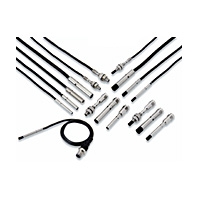
Ultra small size, but surprisingly easy installation!
Related Contents
- Features
- Lineup
- Specifications
- Dimensions
- Catalog / Manual / CAD / Software
last update: December 4, 2014
| Size | 3 dia. | 4 dia. | 5.4 dia. | |||
|---|---|---|---|---|---|---|
| Type | Shielded | Unshielded | Shielded | Unshielded | Shielded | |
| Model | E2E-
C03SR8[] |
E2E-
C03N02[] |
E2E-
C04S12[] |
E2E-
C04N03[] |
E2E-
C05S01[] |
|
| Sensing distance
(at 23°C) |
0.8 mm
±10% |
2 mm
±10% |
1.2 mm
±10% |
3 mm
±10% |
1mm
±10% |
|
| Setting distance *1
(Sensing distance × 0.7) |
0 to 0.56
mm |
0 to 1.4
mm |
0 to 0.84
mm |
0 to 2.1
mm |
0 to 0.7
mm |
|
| Differential travel | 15% max. of sensing distance | |||||
| Detectable object | Ferrous metal (The sensing distance decreases with non-ferrous metal. Refer to Engineering Data on Catalog.) | |||||
| Standard sensing
object |
Iron, 3 × 3
× 1 mm |
Iron, 6 × 6
× 1 mm |
Iron, 4 × 4
× 1 mm |
Iron, 9 × 9
× 1 mm |
Iron, 5.4 × 5.4
× 1 mm |
|
| Response frequency *2 | 5 kHz | 3.5 kHz | 4 kHz | 2 kHz | 4 kHz | |
| Power supply voltage *3 | 10 to 30 VDC (including 10% ripple (p-p)) | |||||
| Current consumption | 10 mA max. | |||||
| Control
output *4 |
Load current | 50 mA max. | 100 mA max. | |||
| Residual
voltage |
2 V max. *5 | |||||
| Indicators | Operation indicator: Yellow (complies with European standard EN60947-5-2) Lights during output. | |||||
| Operation mode | B1/B2: PNP open collector, C1/C2: NPN open collector
B1/C1 models: NO, B2/C2 models: NC |
|||||
| Protection circuits | Output reverse polarity protection, Power source circuit reverse polarity protection, Surge suppressor, Load short-circuit protection | |||||
| Ambient
temperature range |
Operation and storage: -25 to 70°C (with no icing or condensation) | |||||
| Ambient
humidity range |
Operation and storage: 35% to 95% (with no condensation) | |||||
| Temperature
influence |
±15% max. of sensing distance at 23°C within temperature range of -25 to 70°C | |||||
| Voltage influence | ±2.5% max. of sensing distance at rated voltage in the rated voltage ±15% range | |||||
| Insulation resistance | 50 MΩ min. (at 500 VDC) between current-carrying parts and case | |||||
| Dielectric strength | 500 VAC, 50/60 Hz for 1 minute between current-carrying parts and case | |||||
| Vibration resistance | Destruction: 10 to 55 Hz, 1.5-mm double amplitude for 2 hours each in X, Y, and Z directions | |||||
| Shock resistance | Destruction: 500 m/s2 10 times each in X, Y, and Z directions | |||||
| Degree of protection | IEC 60529 IP67, in-house standards: oil-resistant *6 | |||||
| Con-
necting method |
Pre-wired
Models |
Yes | Yes | Yes | ||
| M8 Pre-wired
Connector Models |
Yes | Yes | No | |||
| M8 Connector
Models |
No | Yes | No | |||
| Weight
(packed state) |
Pre-wired
Models |
Approx.
25 g |
Approx.
30 g |
Approx.
35 g |
Approx.
35 g |
Approx.
35 g |
| M8 Pre-wired
Connector Models |
Approx.
20 g |
Approx.
20 g |
Approx.
15 g |
Approx.
20 g |
--- | |
| M8 Connector
Models |
--- | --- | Approx.
10 g |
Approx.
10 g |
--- | |
| Materi-
als |
Case | SUS303 (EN 1.4305) *7 | Nickelplated
brass |
|||
| Sensing
surface |
Heat-resistant ABS | |||||
| Clamping
nuts *8 |
No | |||||
| Toothed
washer *8 |
No | |||||
| Cable | Polyvinyl chloride (PVC) | |||||
| Acces-
sories |
Instruction
manual |
Yes | ||||
| Model label | Yes | |||||
| Mounting
brackets |
Sold separately | |||||
| Size | 6.5 dia. | M4 | M5 | ||||
|---|---|---|---|---|---|---|---|
| Type | Shielded | Unshielded | Shielded | Unshielded | Shielded | Unshielded | |
| Model | E2E-
C06S02[] |
E2E-
C06N04[] |
E2E-
S04SR8[] |
E2E-
S04N02[] |
E2E-
S05S12[] |
E2E-
S05N03[] |
|
| Sensing distance
(at 23°C) |
2 mm
±10% |
4 mm
±10% |
0.8 mm
±10% |
2 mm
±10% |
1.2 mm
±10% |
3 mm
±10% |
|
| Setting distance *1
(Sensing distance × 0.7) |
0 to 1.4
mm |
0 to 2.8
mm |
0 to 0.56
mm |
0 to 1.4
mm |
0 to 0.84
mm |
0 to 2.1
mm |
|
| Differential travel | 15% max. of sensing distance | ||||||
| Detectable object | Ferrous metal (The sensing distance decreases with non-ferrous metal. Refer to Engineering Data on Catalog.) | ||||||
| Standard sensing
object |
Iron, 6.5 × 6.5
× 1 mm |
Iron, 12 × 12
× 1 mm |
Iron, 3 × 3
× 1 mm |
Iron, 6 × 6
× 1 mm |
Iron, 4 × 4
× 1 mm |
Iron, 9 × 9
× 1 mm |
|
| Response frequency *2 | 3 kHz | 3 kHz | 5 kHz | 3.5 kHz | 4 kHz | 2 kHz | |
| Power supply voltage *3 | 10 to 30 VDC (including 10% ripple (p-p)) | ||||||
| Current consumption | 10 mA max. | ||||||
| Control
output *4 |
Load current | 200 mA max.
(60 to 70°C: 100 mA) |
50 mA max. | 100 mA max. | |||
| Residual
voltage |
2 V max. *5 | ||||||
| Indicators | Operation indicator: Yellow (complies with European standard EN60947-5-2) Lights during output. | ||||||
| Operation mode | B1/B2: PNP open collector, C1/C2: NPN open collector
B1/C1 models: NO, B2/C2 models: NC |
||||||
| Protection circuits | Output reverse polarity protection, Power source circuit reverse polarity protection, Surge suppressor, Load short-circuit protection | ||||||
| Ambient
temperature range |
Operation and storage: -25 to 70°C (with no icing or condensation) | ||||||
| Ambient
humidity range |
Operation and storage: 35% to 95% (with no condensation) | ||||||
| Temperature
influence |
±15% max. of sensing distance at 23°C within temperature range of -25 to 70°C | ||||||
| Voltage influence | ±2.5% max. of sensing distance at rated voltage in the rated voltage ±15% range | ||||||
| Insulation resistance | 50 MΩ min. (at 500 VDC) between current-carrying parts and case | ||||||
| Dielectric strength | 500 VAC, 50/60 Hz for 1 minute between current-carrying parts and case | ||||||
| Vibration resistance | Destruction: 10 to 55 Hz, 1.5-mm double amplitude for 2 hours each in X, Y, and Z directions | ||||||
| Shock resistance | Destruction: 500 m/s2 10 times each in X, Y, and Z directions | ||||||
| Degree of protection | IEC 60529 IP67, in-house standards: oil-resistant *6 | ||||||
| Con-
necting method |
Pre-wired
Models |
Yes | Yes | Yes | |||
| M8 Pre-wired
Connector Models |
Yes | Yes | Yes | ||||
| M8 Connector
Models |
Yes | No | Yes | ||||
| Weight
(packed state) |
Pre-wired
Models |
Approx.
55 g |
Approx.
55 g |
Approx.
30 g |
Approx.
30 g |
Approx.
35 g |
Approx.
40 g |
| M8 Pre-wired
Connector Models |
Approx.
20 g |
Approx.
25 g |
Approx.
20 g |
Approx.
20 g |
Approx.
20 g |
Approx.
20 g |
|
| M8 Connector
Models |
Approx.
10 g |
Approx.
15 g |
--- | --- | Approx.
15 g |
Approx.
15 g |
|
| Materi-
als |
Case | SUS303 (EN 1.4305) *7 | |||||
| Sensing
surface |
Heat-resistant ABS | ||||||
| Clamping
nuts *8 |
No | SUS430 (EN 1.4016) *7 | |||||
| Toothed
washer *8 |
No | SUS303 (EN 1.4305) *7 | |||||
| Cable | Polyvinyl chloride (PVC) | ||||||
| Acces-
sories |
Instruction
manual |
Yes | |||||
| Model label | Yes | ||||||
| Mounting
brackets |
Sold separately | ||||||
*1. Using within the set distance enables high-speed responsiveness and a more stable repeat accuracy.
*2. The response frequency is an average value.
*3. When used at a power of 12 V, the Sensor is less susceptible to the effects of internal self heat generation and
therefore a more stable repeat accuracy can be obtained.
*4. When the control output is 20 mA or less, the Sensor is less susceptible to the effects of internal self heat
generation and therefore a more stable repeat accuracy can be obtained.
*5. 3 dia., M4: load current 50 mA, cable length 2 m
4 dia., 5.4 dia., M5: load current 100 mA, cable length 2 m
6.5 dia.: load current 200 mA, cord length 2 m
*6. Oil resistance in-house standard: Performance with respect to water insoluble oil. (Test at right)
*7. Material name in EN standards.
*8. Clamping nuts: 2 pieces, toothed washer: 1 piece
Oil resistance test
After the test time elapses, the characteristics below are checked for problems.
(1) Visual appearance (no damage that affects product characteristics)
(2) Operation check (ON/OFF)
(3) Insulation resistance (50 MΩ min. at 500 VDC)
(4) Dielectric strength (500 VAC, 1 min.)
(5) Water resistance (IP67)
last update: December 4, 2014